Aeotec Door / Window Sensor 7 Pro.
Aeotec Door / Window Sensor 7 was developed to record the condition of doors or windows with Z-Wave Plus. It is powered by Aeotec’s Gen7 technology and S2 framework. You can find out more about Door / Window Sensor 7 Pro by following that link.
To see whether Door / Window Sensor 7 Pro is known to be compatible with your Z-Wave system or not, please reference our Z-Wave gateway comparison listing. The technical specifications of Door / Window Sensor 7 Pro can be viewed at that link.
Package contents:
- Sensor Unit.
- Cover
- Big Magnet.
- Small Magnet.
- Double-Sided Tape large (×2).
- Double-Sided Tape small (x2).
- Screws (×4).
- Dowels( x4).

Important safety information.
Please read this and other device guides carefully. Failure to follow the recommendations set forth by Aeotec Limited may be dangerous or cause a violation of the law. The manufacturer, importer, distributor, and/or reseller will not be held responsible for any loss or damage resulting from not following any instructions in this guide or in other materials.
Keep the product and batteries away from open flames and extreme heat. Avoid direct sunlight or heat exposure. Always remove all batteries from products that are being stored and not used. Batteries may damage the appliance if they leak. Do not use rechargeable batteries. Ensure correct polarity when inserting the batteries. Improper battery use may damage the product.
Door / Window Sensor 7 is intended for indoor use in dry locations only. Do not use in damp, moist, and/or wet locations.
Quick Start
Pre-Installation of Door / Window Sensor 7 Pro.
- Open the cover by pressing the clip on the side and pulling the cover upwards.
- Insert a fresh 1 * 1/2 AA battery, but pay attention to the polarity

Install your Door / Window Sensor 7.
The sensor can be mounted either on the moving part or on the fixed part of a door or a window. Mounting can be accomplished either using the tape by peeling off the protection foil or using two screws with the holes inside the battery compartment. If the tilt detection on a window (only normal windows, no roof windows) shall be used the sensor device must be placed on the moving part of the window and the magnet on the window frame. The sensor comes with two types of magnets:

- The standard magnet covered by plastic part, mountable beside the sensor. Make sure the two indicating lines on sensor enclosure and magnet are opposite to each other. The image on the right-hand-side shows the position of magnet and sensor body.
- A slim "naked" magnet to be mounted behind the sensor in case the sensor body is placed on the side of a window.
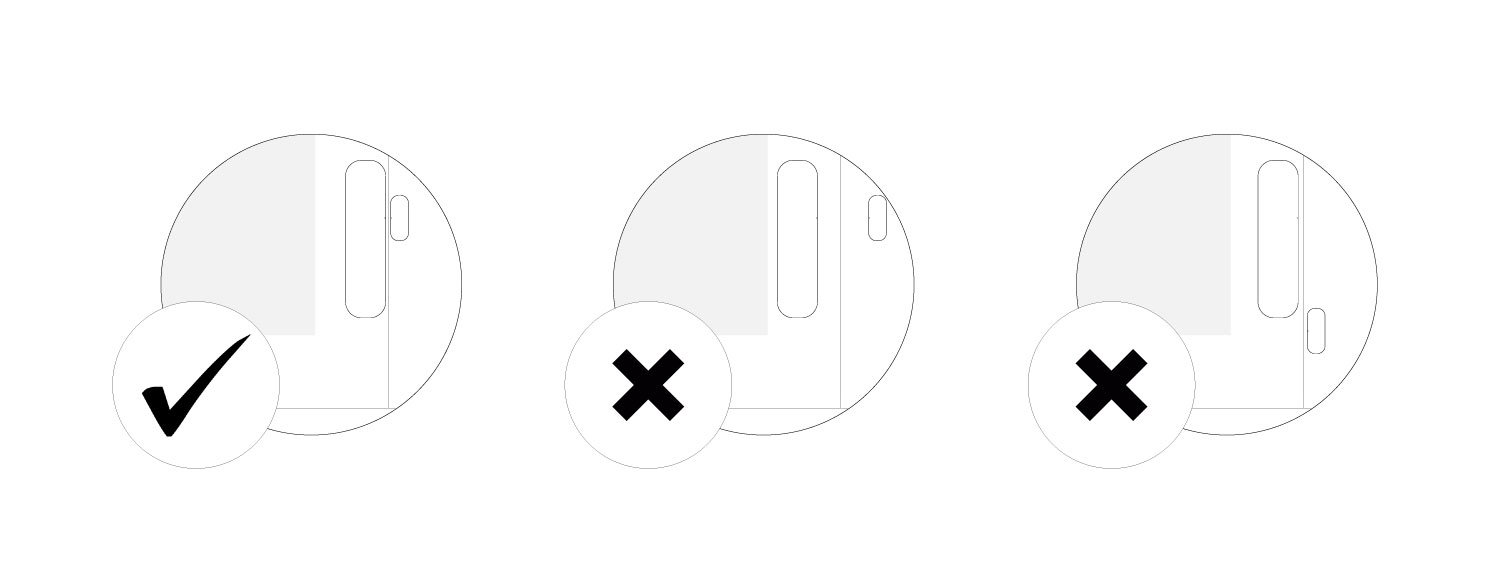
When installing the flat magnet in a hidden location, make sure that it is on the longer side as seen from the mark on the Door / Windows Sensor 7 Pro.

Adding your Door / Windows Sensor 7 Pro to Z-Wave network.
Gateway/Hub guides.
You can find specific instructions for pairing and troubleshooting for the listed Z-Wave gateway/hubs that support this device.
SmartStart Inclusion.
You can use this method of inclusion only if your Z-Wave gateway/controller/hub supports SmartStart.
- Open up your Z-Wave gateway/controller/app.
- Select SmartStart inclusion.
- Scan the QR code located on the Door/Window Sensor 7.
- Within 10 minutes after powering your Door/Window Sensor 7, it will automatically get included in your Z-Wave gateway/controller/hub.
Classic Inclusion
- Set your Z-Wave controller into pairing mode.
- Triple-click the tamper switch on Door / Window Sensor 7 - this begins to blink green/red.
- After completion of the inclusion, Close the cover.
Note: Closing the cover is important! If the housing is not closed, the sensor is permanently awake. Only when the cover is closed does the sensor change to the idle state.
Functions of Door / Window Sensor 7.
Magnetic or Dry Contact Sensor
Once installed, the sensor will report open or close via the Notification command class to indicate a change in state to the Z-Wave controller that it is paired to. By default the magnetic sensor is used instead of the Dry Contact Sensor. If the unit was changed to a dry contact sensor, the internal magnetic sensor will stop performing reports.
- Open/Close utilizes Notification Report.
Tamper
- Tamper utilizes Notification Report.
Tilt detection
The tilt detection allows reporting the way a window is opened. This is accomplished using the command class "binary sensor - tilt-type".
In case the window is closed or opened without tilting the tilt sensor will report "Off". In case the window is tilted an "On" is reported. The angle of inclination of the window must be at least 5°.
- Tilt Sensor uses Binary Sensor Report.
- Tilt Sensor reports Open when the window is opened (with magnetic moving away), and tilted at the same time.
- Binary Sensor Report = 0xFF
- When Window is closed, both Tilt Sensor and Window access will report CLOSED.
- Binary Sensor Report = 0x00
Screw Terminal.
With parameter #1 you can choose between the internal magnet or the external connections such as push buttons or dry contact sensors

- #1: Ground
- #2: Digital Input
- #3: VCC (direct battery supply)
- VCC + Ground terminals can be used to externally power the sensor.
- Digital + VCC is used to connect the external dry contact.
Warning: If using permanent power using VCC and Ground, do not add battery power to the unit. Doing so will result in the destruction of your sensor and void warranty.
Dry contact sensor.
Door / Window Sensor 7 can be converted to any type of sensor utilizing NO (Normally Open) dry contact sensors. This can be used to detect water, magnet positions, tilt, doorbells, etc. To get a more in-depth instruction set, you can follow this link here.

You can wire any dry contact sensor output to Terminal #2 and #3 (it doesn't matter which terminal is wired to where). Dry contact terminals are only looking for Open/Close control which will have Door / Window Sensor 7 report its status depending on the state of the dry contact output to Door / Window Sensor 7.
- Refer to section "Parameter Configurations"
Parameter 1 will determine what mode the Door / Window Sensor 7 is used as.
Communication test.
This utilizes the Power Level command class to determine the health between the Door / Window Sensor 7 and your Z-Wave gateway. This will tell you if the Door / Window Sensor 7 has a healthy connection to your system and is a great method of debugging connectivity issues.
- Set Parameter #5 to value #1
- Double click the Tamper Switch.
- Result:
- Blinks once - success
- Blinks 3x times - failure
Scene Controller.
When activated by configuration parameter #14 the device can perform as a scene controller. The external dry contact will then act as a scene controller with a total of 3 scenes that can be activated.
Parameter #1 must be set to 0, if using a dry contact sensor (Parameter 1 = , the option of Central Scene is disabled.
Here is a list of scene IDs based on momentary button presses.
- Contact tapped 1 time = Scene ID 0
- Contact released = Scene ID 1
- Contact held down = Scene ID 2
Firmware-Update over the Air.
This device is capable of receiving a new firmware 'over the air'. The update function needs to be supported by the central controller. Once the controller starts the update process, perform the following action to confirm the firmware update:
- Wake Up the device by removing the cover.
- The hit the tamper switch once.
Send a wake-up notification.
In order to send your sensors new configuration commands from your Z-Wave controller or gateway, it will need to be woken up.
- Remove the plastic shell cover from DWS7.
- Queue any command, or send a command using your Z-Wave gateway.
- The hit the tamper switch once.
Remove your Door / Window Sensor 7 Pro from Z-Wave network.
Your sensor can be removed from your Z-Wave network at any time. You'll need to use your Z-Wave network's main controller/gateway. To do this, please refer to the part of your gateway's respective manual that tells you how to remove devices from your network.
- Set your Z-Wave controller into unpair mode.
- Triple-click the tamper switch on Door / Window Sensor 7 within 1.5 seconds.
- After a successful exclusion, it will green light up its LED for 2 seconds then deactivate.
Reset your Door / Windows Sensor 7 Pro.
This device also allows being reset without any involvement of a Z-Wave controller. This procedure should only be used when the primary controller is inoperable.
To manually factory reset:
- Remove the cover of Door / Window Sensor 7
- Press and hold the tamper switch for ~5 seconds until the red LED lights up.
- Immediately Release the tamper switch, and then quickly press and hold the tamper switch again, the LED will flash red 3 times while holding it before the green LED indicator.
- A green LED will confirm reset and immediately revert to flashing the red LED 5x more times, you may release the tamper switch at any point in time during the green LED or anytime afterward.
Association Groups.
Association groups allow Door Window Sensor 7 to directly control Z-Wave devices without the use of a Z-Wave Controller to maximize communication efficiency.
By default, Group 1 is assigned to Node Id 01 during the pairing process of your Door / Window Sensor 7 to determine where it should report its sensor reports to.
| Group Number | Maximum Nodes | Description |
| 1 | 5 | Lifeline |
| 2 | 5 | Control devices when a magnet or external dry contacts trips |
| 3 | 5 | Sends our alarm message when magnet controlled or external dry sensor trips. |
| 4 | 5 | Sends alarm messages when tamper is tripped |
| 5 | 5 | Control devices when tilting sensor trips |
Parameter Configurations.
Parameter 1: Operation Mode.
This parameter allows switching between internal sensor and external sensor.
Size: 1 Byte, Default Value: 0
| Setting | Description |
| 0 | Magnet Sensor |
| 1 | External / Dry Contact |
Parameter 2: Dry Contact Operation Mode
Parameter defines how dry contact will operate with the sensor or switch that is connected to the dry contact terminals.
Size: 1 Byte, Default Value: 0
| Setting | Description |
| 0 | NO Toggle / Follow state will follow the input of the dry contact terminals where OFF is CLOSED, and ON is OPEN. |
| 1 | NC Toggle / Follow state will follow the input of the dry contact terminals where ON is CLOSED, and OFF is OPEN. |
| 2 | NO save state will allow state of sensor to toggle OPEN/CLOSE based on OFF to ON signal. |
| 3 | NC save state will allow state of sensor to toggle OPEN/CLOSE based on ON toOFF signal. |
Parameter 3: Door/Window State.
This parameter allows setting Door / Window Sensor 7 state when the magnet is close to the sensor.
Size: 1 Byte, Default Value: 0
| Setting | Description |
| 0 | closed when the magnet is near |
| 1 | opened when the magnet is near |
Parameter 4: Visual LED Indications.
This parameter defines events indicated by the visual LED indicator. Disabling events might extend battery life.
Size: 1 Byte, Default Value: 7, Range: 0 - 7
| Setting | Description |
| 0 | no indications |
| 1 | indication of opening/closing status change |
| 2 | indication of wake up (1 x click or periodical) |
| 4 | indication of device tampering |
Parameter 5: Range test after double click.
Allows enabling the activation of Z-Wave range test with double click of a Tamper Switch 2.
Size: 1 Byte, Default Value: 0
| Setting | Description |
| 0 | Disable |
| 1 | Enable |
Parameter 6: Group 2 Association Triggers.
This parameter defines events that result in sending On/Off commands to devices added to the 2nd Association Group. These commands are sent alternately to switch the devices On and Off. Commands represent the values of BASIC SET command frames. This parameter is inactive in external dry-contact mode (parameter “Operation Mode” set to 1).
Size: 1 Byte, Default Value: 0
| Setting | Description |
| 0 | switch after opening and closing |
| 1 | switch after opening |
| 2 | switch after closing |
Parameter 7: Commands sent to associated devices on Group 2.
Command frames sent to devices added to the 2nd association group.
Size: 1 Byte, Default Value: 2
| Setting | Description |
| 0 | On |
| 1 | Off |
| 2 | On and Off |
Parameter 8: Values of ON command frame sent to Group 2 Association.
The value of 0 turns OFF the device, 255 turns it On. In the case of associating the Dimmer or Roller Shutter module, values
Size: 1 Byte, Default Value: 255
| Setting | Description |
| 0 - 99 | allow setting an Associated device to a specified level (0 is OFF) |
| 255 | ON |
Parameter 9: Value of OFF command frame sent to Group 2 Association.
The value of 0 turns OFF the device, 255 turns it On. In the case of associating the Dimmer or Roller Shutter module, values.
Size: 1 Byte, Default Value: 0
| Setting | Description |
| 0 - 99 | allow setting an associated device to a specified level. (0 is OFF) |
| 255 | ON |
Parameter 10: Time Delay of ON command from Group #2.
The time period after which On command frame will be sent.
Size: 2 Byte, Default Value: 0
| Setting | Description |
| 0 - 32400 | Time set in seconds |
Parameter 11: Time Delay of OFF command from Group #2.
The time period after which the OFF command frame will be sent.
Size: 2 Byte, Default Value: 0
| Setting | Description |
| 0 - 32400 | Time in seconds |
Parameter 12: Delay of tamper alarm cancellation.
The time period after which a tamper alarm will be canceled.
Size: 2 Byte, Default Value: 0
| Setting | Description |
| 0 - 32400 | Time in seconds |
Parameter 13: Reporting tamper alarm cancellation.
Reporting cancellation of tamper alarm to the controller and 3rd Association Group.
Size: 1 Byte, Default Value: 1
| Setting | Description |
| 0 | do not send tamper cancellation report |
| 1 | send tamper cancellation report |
Parameter 14: Central Scene Event Functionality
This parameter enables/disables the central scene function.
Size: 1 Byte, Default Value: 0
| Setting | Description |
| 0 | Disabled |
| 1 | Enable |
Parameter 15: Tilt Sensor Functionality
This parameter enables/disables the tilt function.
Size: 1 Byte, Default Value: 1
| Setting | Description |
| 0 | Disabled |
| 1 | Enable |
Parameter 16: Tilt Sensor State
This parameter allows to set in what state is door/window when the tilt is in an OFF state.
Size: 1 Byte, Default Value: 0
| Setting | Description |
| 0 | OFF when sensor is vertical |
| 1 | ON when sensor is vertical |
Parameter 17: 5th Association Group Trigger
This parameter defines the status of the magnet switch that causes sending a BASIC command to all devices of Association Group 5.
Size: 1 Byte, Default Value: 0
| Setting | Description |
| 0 | Switch after Open and Close |
| 1 | Switch after Open |
| 2 | Switch after Close |
Parameter 18: Command Sent to Devices of Association Group 5
This parameter defines which commands is sent to 5th Association Group
Size: 1 Byte, Default Value: 2
| Setting | Description |
| 0 | On |
| 1 | Off |
| 2 | On and Off |
Parameter 19: BASIC command value sent to 5th Association Group on On event
This is the BASIC command value sent in case of On event.
Size: 1 Byte, Default Value: 255
| Setting | Description |
| 0 - 99 | allow setting an associated device to a specified level. (0 is OFF) |
| 255 | ON |
Parameter 20: BASIC command value sent to 5th Association Group on Off event
This is the BASIC command value sent in case of Off event.
Size: 1 Byte, Default Value: 0
| Setting | Description |
| 0 - 99 | allow setting an associated device to a specified level. (0 is OFF) |
| 255 | ON |
Parameter 21: Tilt sensitivity
With this parameter, you can adjust the tilt sensitivity if the tilt is too low or too strong. Value 0 does not disable Tilt Sensor, it just sets it to a minimum.
Size: 1 Byte, Default Value: 50
| Setting | Description |
| 0 - 100 | Time in seconds |
Parameter 255: Factory reset.
This parameter helps reset configuration parameters and the device to factory defaults.
Size: 1 Byte, Default Value: 0
| Setting | Description |
| 1 | Reset Parameter |
| 1431655765 | Factory default (exclude the device) |